Thermocouple Circuit Schematic Thermocouple Signal Condition
Thermocouple circuit construction simple figure Block diagram of the thermocouple conditioning circuit. Thermocouple: what is it? how does it work? types of
Simple Thermocouple Amplifier Circuit - Circuit Diagram
Uncategorized archives K type thermocouple diagram Thermocouple experimental evaporator
Thermocouple circuit schematic
Thermocouple temperature junctions tip meter connector thermocouples j2 j1 wiresThermocouple principle Thermocouple circuit working diagram principle its applications definitionThermocouple schematic.
Thermocouple circuit diagramThermocouple circuit diagram Thermocouple schematic diagramExplanation of thermocouple with circuit.

Thermocouple figure
How to play with thermocouplesThermocouple diagram, circuit, construction, applications (a) schematic diagram of the experimental setup, (b) thermocoupleThermocouple complete guide with arduino interfacing.
Thermocouple thermistor eletimes linquip simplified figure1Figure 1-4. typical thermocouple circuits Thermocouple principleUnderstand the thermocouple circuit working principle and its.

Thermocouple measurement thermopile working
Thermocouple amplifier schematicThermocouple measurement junctions thermocouples cable wires indicator joining Thermocouple : working principle and its applicationsThermocouple wiring schematic.
What is a thermocouple and how does it work?Thermocouple circuit diagram Temperature measurements with thermocouples ~ learning instrumentationThermocouple types, junctions, connector and tip styles.

Thermocouple-working,types-e,j,k,t,s,r,grounding,thermopile,advantages
Thermocouple diagram in 2021Thermocouple circuit basic explanation control Thermocouple work does working diy type sensor types its temperature measure which consistsSchematic thermocouple amplifier hackaday.
Thermocouple temperature instrument connection junction sensor schematic thermocouples basic cold control diagram measurement wire measuring sensors electrical engineering simple wiresA typical circuit diagram of a thermocouple Simple thermocouple amplifier circuitThermocouple construction.

Thermocouple types, junctions, connector and tip styles
Thermocouple circuit junction measuring seebeck heat mot forskjellige lyden hverandre betydning metaller termokopel effect instrumentMax6675 thermocouples play circuit datasheet electroschematics Working thermocouple principle temperature thermocouples sensor work cold used omega diagram do voltage engineering probe principles responseThermocouple wiring schematic.
Schematic diagram of a thermocoupleHow does a thermocouple work? working principle and operation. Thermocouple signal conditioning: challenges and solutions.


(a) Schematic diagram of the experimental setup, (b) thermocouple

voltage - Please fix my broken understanding of this simple
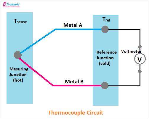
Thermocouple Diagram, Circuit, Construction, Applications - ETechnoG

Uncategorized Archives - Electrical & Automation Solutions

thermocouple circuit diagram - Wiring Diagram and Schematics

Thermocouple Diagram in 2021 | Circuit, Diagram, Electronics circuit

thermocouple circuit diagram - Wiring Diagram and Schematics